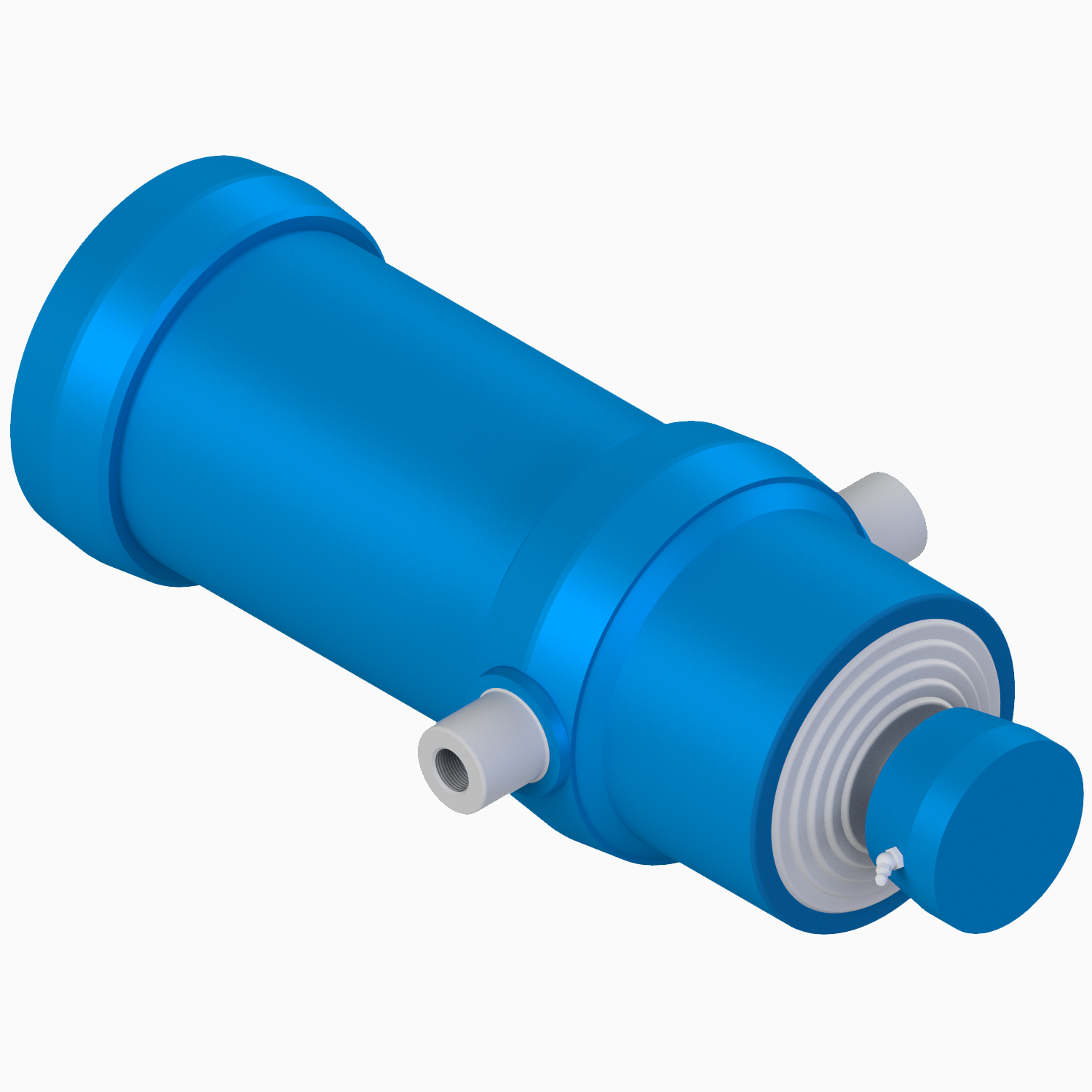
Single-acting telescopic cylinders
- maximum working pressure: 220 bar (22 Mpa)
- maximum nubmer of stages: 10
- maximum stroke: 6.315mm
Further information
Wherever conventional hydraulic cylinders are not used due to their design, especially in narrow environments, our telescopic cylinders offer THE solution. Whereby axial load ensures the best working conditions, i.e. that the cylinders work in vertical position upwards or downwards. Our hydraulic telescopic cylinders are available in different stages and differ in different diameters and strokes.
Please ask for special requirements such as non-rotating piston rod, elastic damping, magnetic piston and ISO mounting dimensions separately when ordering.
Our models:
-
single acting
-
double acting
-
synchronous system
-
up to 12.000 mm stroke length
-
to working pressure 175 / 225 bar until arrester
-
bronze guide, modifiable
-
double rod respectively synchronization
Technical Information
Materials:
The production of our telescope cylinders is carried out with seamless drawn tube:
- Cylinder tube: St. 52 DIN to 1629 R=500 to 650 N/mm² Rs=355 N/mm²
- Bottom: MW 450 20 Mn V 6 R=550 to 720 N/mm² Rs=420 N/mm²
- ball pan: Fe 510 R=450 to 630 N/mm².
Pull-out elements:
The used salt and nitrile treatment with the description "method TUFFTRIDE TF1 Degussa" enables the abandonment of bronze bearings or guide rings for the pull-out elements, because the surface is in a great extent consistent against wear and milling. In particular, a high surface hardness from HV-5/12 = 500 to 550 will be scored.
Thanks to the mentioned benefits, the pull-out elements exhibit no corresponding bronze bearings or ring seats. This grants them an substantially above the commercial standard mechanical resistance.
All of this also enables the production of a longer guiding and operation the cylinder at the end stroke under maximum pressure.
Surface:
In the first step, the outside surface of the pull-out elements will be polished and rolled; this way a roughness of 0.10 to 0.25 µm will be scored.
Seals:
The special formed seals and wiper seals consist of polyurethane:
- temperature: -40 to +110° C.
- maximum pressure: 400 Kg/cm² (395 Bar)
- maximum speed: 0,5 m/sec
- mineral hydraulic and daub fluids
Decline:
All cylinders are tested finally with hydraulic pressure from 240 kg/cm² (235bar). Cylinders with diameter 240 are tested with hydraulic pressure from 205kg/cm² (200 bar).
General operating and maintenance instruction, safety instruction
1. Instruction of usage
The hydraulic telescope cylinder is designed for installation in vehicles that meet the essential safety requirements of the Machinery Directives 98/37 EWG, as well as their later changes and the provisions for vehicles effective norms (UNI 10691-10692-10693-10694-10695).
1.1 Instruction of surrounding area
The extendible parts of the cylinder are susceptible to corrosion, if they are inserted in very aggressive surrounding area or extended for longer time than neccessary for the normal dumping process. If these conditions can not be avoided, we recommend the use of cylinders with chrome rods. The sealing parts (seals, oil scraper) inside the telescopic hydraulic cylinder allow use at temperatures (surrounding area temperature and hydraulic oil temperature) between -40 ° C and + 95 ° C.
1.2 Standard operation
The standard operation of hydraulic telescope cylinder provides that it is used for vehicle lift and that it is used for the advanced tilting of the on the vehicle presented freight above the total stroke length under attention of the boundary value of the cylinder according to the details of the technical documentation and identification shield. In addition, it has to make sure, that the cylinder is designed for direct freights along its axis, that means that the vehicle is not allowed to be construed on the side or construed as construction piece. Because of this, the hydraulic telescope cylinder is not able to tilting over; otherwise, please note, that it can be damaged when the vehicle tilting over.
1.3 Control of dimensions
The weight of the vehicle lift and the weight of the freight yield the dumping total weight, which normally is described as "stroke force". The mentioned "stroke force" in the technical documentation is a purely guideline and serves as first criterion for the choice of the cylinder. The maximum "stroke force" can exclusively by the competent technicians for assembly on the basis of vehicle geometry, the required use, the maximum thrust as well as the maximum allowable pressure of the cylinder is calculated. Thereby, the assembly technician has to make sure, that the maximum thrust and the allowed maximum pressure will not be exceeded with use of the hydraulic telescope cylinder. In addition, the technician has to test the maximum reachable angle from the vehicle lift based on the vehicle geometry and cylinder stroke.
This takes into account that
a) the cylinder is not allowed to reach the stroke end (UNI 10693- 4.2.2)
b) the vehicle lift in transport position is not allowed to lie on the cylinder
c) the maximum permissible angle between cover and bottom is 30 °.


